
VHS Glitch Shader for Compose — From Zero to Production
I’ve always wanted to create UI that shows mood, not just content. I want it to be emotional, not just functional.
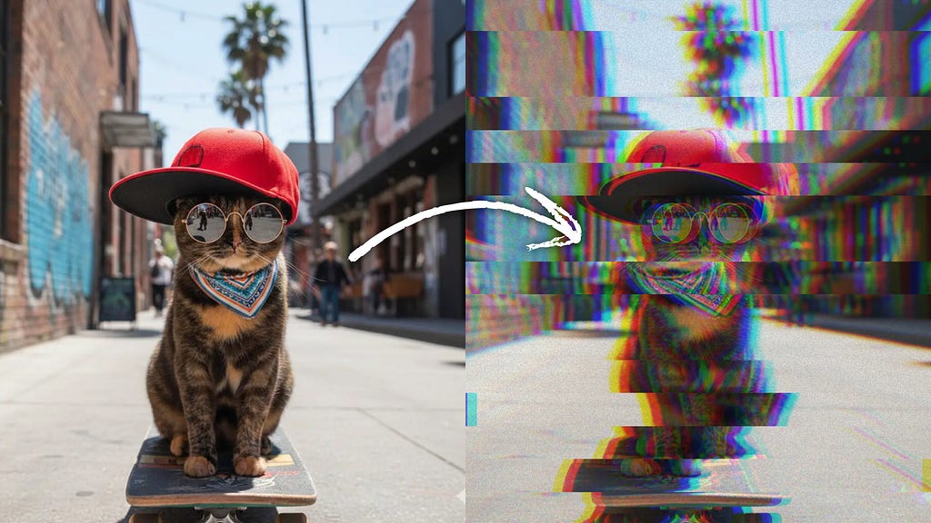
So I built this:
One modifier. And any Compose element gets VHS glitch aesthetic.
The complete code is at the bottom; grab it and go. Or follow the steps with me, and next time you’ll make your own custom shader from scratch.
How Shaders Think
The beauty of AGSL is that it works on a per-pixel basis. For each pixel on the screen, the shader receives the pixel coordinates, and you specify the color to output. That’s all there is to it.
Understanding UV Coordinates
Before we get into code, let’s grasp UV coordinates. They are the foundation of everything we will create.
In shader programming, every pixel has a position represented by UV coordinates:
- U (or X): The horizontal position, ranging from 0.0 (left edge) to 1.0 (right edge)
- V (or Y): The vertical position, ranging from 0.0 (top edge) to 1.0 (bottom edge)
When we adjust these coordinates before sampling the source image, we create distortion effects. We are not moving pixels; instead, we are selecting different source pixels for each output pixel.
Step 1: Create a Static Wave Distortion
Let’s start with the simplest distortion: a static wave pattern. This isn’t a glitch yet, but it introduces the core concept we’ll build upon.
The goal is to shift pixels horizontally based on their vertical position. Each horizontal row slides left or right by a small amount, creating a wave-like distortion.
uniform shader image;
uniform float2 imageSize;
uniform float intensity;

vec4 main(vec2 fragCoord) {
    // Convert fragment coordinates to UV (0.0 to 1.0)
    vec2 uv = fragCoord / imageSize;

    // Create a wave based on vertical position
    float wave = sin(uv.y * 40.0);

    // Calculate displacement amplitude
    float amplitude = 0.01 * intensity;

    // Shift the X coordinate based on the wave
    uv.x += wave * amplitude;

    // Sample the image at the displaced position
    return image.eval(uv * imageSize);
}
What’s happening here:
- fragCoord / imageSize normalizes pixel coordinates to the 0–1 range, making our math resolution-independent.
- sin(uv.y * 40.0) creates 40 wave cycles across the screen height. The result oscillates between -1.0 and 1.0.
- 0.01 * intensity keeps the base amplitude small (1% of screen width) and allows external control.
- We modify only the X coordinate. The wave value multiplied by amplitude determines the actual shift.
If you see the wavy distortion, the pipeline works. But it’s static and not very glitchy.
Step 2: Animate the Wave
A static wave isn’t interesting, so let’s make it move.
uniform shader image;
uniform float2 imageSize;
uniform float intensity;
uniform float time;

vec4 main(vec2 fragCoord) {
    vec2 uv = fragCoord / imageSize;

    // Add time to the wave equation
    float wave = sin(uv.y * 40.0 + time * 5.0);

    float amplitude = 0.01 * intensity;
    uv.x += wave * amplitude;

    return image.eval(uv * imageSize);
}
The key difference is sin(uv.y * 40.0 + time * 5.0). Adding time * 0.5 inside the sin() function shifts the wave pattern over time. The wave moves at 5 units per second; higher values mean faster movement.
The sine function is periodic. Continuously adding to the input scrolls through the wave pattern, making the distortion appear to flow across the image.

This already looks somewhat glitch-like, but it’s too smooth and predictable. Real glitches do not flow; they jump.
Step 3: Add Horizontal Slices
Now we reach the core of the glitch aesthetic. Instead of shifting individual pixels with a continuous wave, we cut the screen into horizontal bands and jerk them around randomly.
First, we need random functions. AGSL doesn’t have built-in random, so we create a pseudo-random hash:
float rand(float x) {
    return fract(sin(x * 1234.567 + 0.123) * 43758.5453);
}

float rand2(vec2 v) {
    return fract(sin(dot(v, vec2(12.9898, 78.233))) * 43758.5453);
}
These magic numbers are a well-known pseudo-random technique from The Book of Shaders. Shader developers have been copying and pasting them for years. I covered this in detail here.
Now the slice displacement function:
float randDirection(int sliceIndex) {
    return (rand(float(sliceIndex) + 99.0) > 0.5) ? 1.0 : -1.0;
}

vec2 applySliceOffset(vec2 uv) {
    int numSlices = int(slices);
    float sliceHeight = 1.0 / float(numSlices);
    int sliceIndex = int(uv.y / sliceHeight);

    float frame = floor(time);
    float r = rand(float(sliceIndex) + frame + realRandom * 100.0);

    float glitch = 0.0;
    if (r > 0.65) {
        glitch = (r - 0.65) * 4.0 * intensity;
    }

    float direction = randDirection(sliceIndex);
    float offset = glitch * 0.08 * direction;
    uv.x += offset;

    return clamp(uv, 0.0, 1.0);
}
Let’s break it down.
- Calculating slices: With 12 slices, each occupies about 8.3% of screen height. sliceIndex will be 0–11 based on vertical position.
- Temporal randomization: floor(time) quantizes continuous time into discrete frames, so the glitch pattern changes once per second. The combined seed (float(sliceIndex) + frame + realRandom * 100.0) ensures different values for each slice, changes over time, and breaks repeating cycles using external random from Kotlin.
- The threshold mechanism: Only about 35% of slices will glitch (when r > 0.65). The glitch intensity scales with how much r exceeds 0.65. You can adjust 0.65 to control how many slices glitch; lower means more chaos.
- Randomized direction: Each slice independently decides whether to shift left (-1) or right (+1).
If we do it with out time, then we this effect — static slices:
But when we add time logic to it, then we got this:

This already looks like a legitimate glitch effect. Horizontal slice displacement is the signature characteristic of signal interference.
Step 4: Add Chromatic Aberration (RGB Split)
Chromatic aberration occurs when color channels become misaligned. In VHS artifacts, it appears as red halos on one side of the edges and cyan on the other side.
The trick: sample each RGB channel from a different horizontal position.
vec3 sampleRgbSplit(vec2 baseUv) {
    float splitAmount = 0.005 * rgbSplitIntensity;

    vec2 uvR = clamp(baseUv + vec2(-splitAmount, 0.0), 0.0, 1.0);
    vec2 uvG = baseUv;
    vec2 uvB = clamp(baseUv + vec2(splitAmount, 0.0), 0.0, 1.0);

    vec3 cR = image.eval(uvR * imageSize).rgb;
    vec3 cG = image.eval(uvG * imageSize).rgb;
    vec3 cB = image.eval(uvB * imageSize).rgb;

    return vec3(cR.r, cG.g, cB.b);
}
What’s new here:
- We create three UV coordinates: uvR shifted left, uvG unchanged, uvB shifted right.
- We sample the source image three times.
- We take the red channel from the left sample, green from the center, and blue from the right.
- clamp() ensures we don’t sample outside image bounds.
You might wonder: if we’re shifting channels for every pixel, why do we only see color halos at edges? In solid areas, all three shifted samples are the same color, so there is no visible effect. At edges, the samples differ, creating color fringing.
The order matters: apply slice displacement first, then RGB split on the displaced UV: this way, chromatic aberration rides along with the displacement.
Step 5: Add Scan Line Noise
VHS tapes displayed images using horizontal scan lines. When the signal degraded, these lines appeared as alternating dark bands with random interference.
Let’s trace through:
- fract(uv.y * imageSize.y * 0.5) gives us 0 for even rows, 0.5 for odd rows (roughly).
- step(0.5, line) returns 1.0 for odd rows, 0.0 for even — creating the alternating pattern.
- rand2(…) adds random variation per scan line.
- mix(1.0, 0.85, …) darkens affected lines up to 15%.
Step 6: Add Color Bar Artifacts
The most dramatic glitch artifact is complete signal failure, when a slice of video is replaced entirely by a solid color bar. This mimics the rainbow bars that appear on broken VHS tapes.
vec4 getSolidColorBar(vec2 uv) {
    int numSlices = int(slices);
    float sliceHeight = 1.0 / float(numSlices);
    int sliceIndex = int(uv.y / sliceHeight);
    float sliceY = float(sliceIndex) * sliceHeight;

    float rnd = rand2(vec2(intensity * realRandom, sliceY));
    if ((rnd * 2.5 + 0.5) < intensity) {
        if (realRandom > 0.67) {
            return vec4(0.0, 1.0, 0.3, 1.0); // green
        } else if (realRandom > 0.33) {
            return vec4(1.0, 0.0, 0.85, 1.0); // magenta
        } else {
            return vec4(0.0, 0.85, 1.0, 1.0); // cyan
        }
    }

    return vec4(0.0, 0.0, 0.0, 0.0); // No solid color (alpha = 0)
}
The condition (rnd * 2.5 + 0.5) < intensity determines when color bars appear. At low intensity, bars are rare. At high intensity, they appear frequently. Actually, I might use a separate intensity for it. But in the current implementation, I used the same.
Green, magenta, cyan — are classic CRT phosphor colors that evoke vintage electronics.
Step 7: Add Color Tinting
The final touch is a subtle color tint that gives the image a vintage feel.
float brightness = dot(color, vec3(0.299, 0.587, 0.114));
float darkness = 1.0 - brightness;
vec3 tintColor = vec3(0.2, 0.3, 0.35);
color = mix(color, tintColor, darkness * 0.15 * intensity);
This is the standard luminance formula (ITU-R BT.601). The same one has been used on television since the 1980s. We want to tint dark areas more than bright areas, like lifted blacks in film. The result is that dark areas get a subtle blue-gray tint, while bright areas stay mostly unchanged.
Compose Integration
Let’s expose almost all parameters as an API for the modifier:
@Composable
fun Modifier.glitchShader(
    intensity: Float = 1f,
    slices: Float = 16f,
    frameDuration: Int = 16,
    noiseIntensity: Float = 1f,
    colorBarsEnabled: Boolean = false,
    rgbSplitIntensity: Float = 1f,
    isEnabled: Boolean = true,
):
And the usage is pretty straightforward:
Image(
    painter = painterResource(id = R.drawable.sample),
    contentDescription = null,
    modifier = Modifier
        .fillMaxSize()
        .glitchShader(
            intensity = 1.0f,
            slices = 12f,
            colorBarsEnabled = true
        )
)
Final complete glitch effect
This is how the final modifier looks. Almost all parameters are configurable.
Source code
Here is the source code of each step I covered here, a tutorial project:
GitHub – makzimi/android-glitch-shader-tutorial: Android Glitch AGSL Shader Tutorial
And here is just the final snapshot of the shader without all tutorial noise:
GitHub – makzimi/glitch-shader: Android Shader. Glitch effect. AGSL.
More Glitch Shaders!
There’s another excellent article about AGSL glitch effects worth checking out by Konstantin Zolotov. Although both are glitch shaders in AGSL, our implementations are quite different. We share the basic idea of dividing the image into horizontal slices, but everything else pretty much differs. Konstantin did a great job with his approach, and I recommend reading it as well.
Thank you so much for reading my article. I hope you enjoyed it. If you have any questions, suggestions drop me a line in the comments, and I’ll be sure to read them!
And follow me on Twitter. Usually, I post about Android development and software engineering in general.
VHS Glitch Shader for Compose — From Zero to Production was originally published in ProAndroidDev on Medium, where people are continuing the conversation by highlighting and responding to this story.


This Post Has 0 Comments